In a controlled stop, drive motion is brought to a standstill in a controlled manner. The drive commands a zero velocity from the motor. The motor decelerates at the prescribed deceleration value (CS.DEC).
A controlled stop can occur in three ways:
- The user configures a programmable digital input to mode 13 using DINx.MODE. For example, if DIN1.MODE 13 is applied, digital input 1 is set to controlled stop.
- Either a controller or the user (through the WorkBench terminal window) initiates a software disable (DRV.DIS) command .
- A fault initiates a controlled stop from the drive. See Fault and Warning Messages for the faults which initiate a controlled stop.
The controlled stop mechanism is activated in the following cases:
- DRV.DISMODE = 2 and user executes DRV.DIS from the terminal or WorkBench disable buttons.
-
-
You must disable the drive in order to set DRV.DISMODE.
- DRV.DISMODE = 2 and user executes DRV.DIS from a fieldbus connected to the drive.
- A fault occurs which has a controlled stop (CS) reaction. After the CS is executed, the drive disables.
- A digital input mode (DINx.MODE) is set to 13. If the digital input state changes (active high or low according to DINx.INV) the CS is executed, and then the drive disables.
- HW limit switch or SW limit switch:
Configuration:
HW limit switches can be configured via digital input and mode 18 or 19. (See also DINx.MODE)
SW limit switches can be configured through parameters SWLS.LIMIT0/SWLS.LIMIT1.
Activation:
When either a HW or SW limit switch is met, a controlled stop is initiated to stop the motion. The drive will NOT be disabled automatically after the controlled stop has been executed (default configuration), instead it will throw a warning (n107/n108) that a HW/SW limit switch was hit and will stay enabled. The parameter DRV.DISTO is not active. Only a commanded move that deactivates the limit switch will allow normal operation and remove the limit switch warning.
- With a firmware version equal or greater than M_01-18-05-000, the SW limit warning can be configured to create a fault and disable the drive (see FAULT107.ACTION and FAULT108.ACTION).
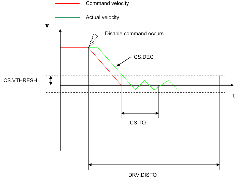
Use the drive CS parameters to configure a controlled stop as follows:
- CS.DEC: Deceleration ramp that is used for disable.
- CS.VTHRESH: Velocity 0 threshold. The motor shaft is considered as stopped as soon as the actual velocity (filtered through a 10 Hz filter, such as VL.FBFILTER) is within ± CS.VTHRESH.
- CS.TO: Velocity 0 time. The actual velocity must be consecutively within 0 ± CS.VTHRESH for the time CS.TO, before the drive completes the CS process. This value is used since the motor can overshoot out of the VEL0 window depending on the gains, deceleration ramp, motor inertia and so on.
- DRV.DISTO: Disable time out. This parameter sets an overall and independent running check as to whether or not the drive can achieve the disable state. If the VEL0 window set in step 3 is too small, it is possible that the drive may never reach the end of the CS process. The DRV.DISTO parameter and functionality addresses this issue by disabling the drive after the DRV.DISTO time elapses, even if the CS process did not end.
Controlled Stop Diagram
When configuring the controlled stop feature, please note the following:
- If the HW limit switch is active and any of the other CS activated, the only difference will be that in this case the DRV.DISTO will limit the time before disabling the drive.
-
If the value of DRV.OPMODE is torque mode, the drive will execute the controlled stop by switching internally to velocity mode. Therefore, it is recommended to tune the velocity loop properly, even though the drive might only be used in torque mode.
- Set DRV.DISTO to an appropriate value that will allow the motor to decelerate from any velocity to 0 with DRV.DEC . This value must also allow the motor to afterwards remain within VL.FB for CS.TO consecutively within 0 ± CS.VTHRESH.
- CS.DEC: Deceleration ramp that is used for the controlled stop.
The drive issues a fault F703 in case that the DRV.DISTO counter expires during a controlled stop procedure. For more information see Controlled Stop in WorkBench Help.
Related Parameters and Commands
CS.STATE : Reads the current state of controlled stop process (0 = controlled stop is not occurring. 1 = controlled stop is occurring).
Related topics: